9V Dual Polarity Power Supply from 9V Battery

9V Dual Polarity Power Supply from 9V Battery

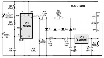
Here the schematic design of 9V dual polarity power supply from 9V battery. Dual-voltage power supply is necessary particularly for running the op-amps and some of the instrumentation amplifiers. Some low-power audio pre-amplifiers also use dual-voltage power source.

This circuit delivers both +9V as well as -9V DC output from a single 9V battery. It contains timer IC NE555 (IC1), negative-voltage regulator IC 7909 (IC2) along with several discrete parts.

Timer IC NE555 is set up as being a free-running oscillator. It generates approximately 100kHz frequency. An audio system would not pick up this frequency since it is above the audible assortment. Therefore a Villard cascade voltage multiplier is applied as the voltage booster. The boosted voltage is produced ripple-free and regulated to -9V by negative-voltage regulator LM7909.

The frequency of the squarewave generator is determined by the values of C1, R1 and R2. The frequency of the signal may slightly change with the temperature variation but the modification in frequency will not have an impact on the output voltage of the circuit.

Capacitors C3, C4, C5 and C6 and diodes D1, D2, D3 and D4 form the Villard cascade voltage multiplier. The output voltage from the Villard cascade voltage multiplier is fed to linear negative-voltage regulator IC2 to remove ripples and get precise -9V DC. Capacitors C7 and C8 present extra noise-filtering. The output from voltage regulator IC2 is -9V.

Build the circuit on a general-purpose PCB and enclose inside a appropriate case. Fix the 9V battery inside the case. At the front panel, connect three terminals for outputs. Take a note that this power supply tend to be utilized only for low-power applications/devices.

9V Dual Polarity Power Supply from 9V Battery, Circuit Source: Electronics For You Mag
Comments

Unknown said…
Could you tell me if the capacitor C2 is used in this project or not?

Popular posts from this blog

LM317T Voltage Regulator Circuit with Pass Transistor

This is the schematic diagram of voltage regulator circuit with pass transostor. The regulator is based regulator IC of LM317T. The LM317T output current can be raised by utilizing an additional power transistor (on circuit, it is 2N2955) to share a portion of the total current. The amount of current sharing is established with a resistor placed in series with the LM317 input and a resistor placed in series with the emitter of the pass transistor. In the above scheme design , the pass transistor will start conducting when the LM317 current reaches about 1 ampere, due to the voltage drop across the 0.7 ohm resistor. Current limiting happens at about 2 amperes for the LM317 which will drop about 1.4 volts across the 0.7 ohm resistor and make a 700 millivolt drop across the 0.3 ohm emitter resistor. Thus the total current is limited to about 2+ (.7/.3) = 4.3 amperes.

Sealed Lead Acid (SLA) 12V Battery Charger with Current Limiting

This is the circuit design of Smart Sealed Lead Acid (SLA) 12V Battery Charger featuretwith Current Limiting. The charger uses a two step process for charging SLA batteries – a current limited ‘fast’ mode followed by a constant voltage ‘float’ mode. Maximum charging current is 1A. An onboard LED indicates when the charger is in ‘fast’ mode. When the LED goes out the battery is charged and the charger has switched to ‘float’ mode.

13.8 Volt 20 A Power Supply

This PSU has been especially designed for current-hungry ham radio transceivers. It delivers safely around 20Amps at 13.8V. For lower currents, a separate current limiting output, capable of 15ma up to a total of 20A has been added. The power transformer should be capable to deliver at least 25A at 17.5 to 20V. The lower the voltage, the lower power dissipation. The rectified current will be “ironed” by the C1, whose capacity should not be less than 40.000uF, (a golden rule of around 2000uF/A), but we recommend 50.000uF. This capacity can be built up by several smaller capacitors in parallel. The base of this design is a simple 12V regulator (7812). The output voltage can be brought to desired value (here 13.8V) by two external resistors (R5 and R6) using this formula: U= 12(1+R5/R6) The low currents (here 15mA) will keep the 7812 in its regular function. As soon as the current rises over 15ma, the voltage drop on R4 will “open” the Q3, actually handling the high output current. Thi